 Lite Simo
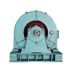
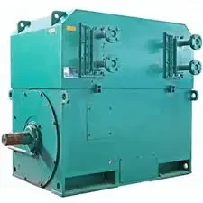
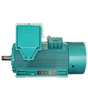
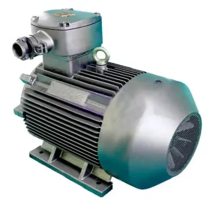
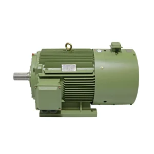
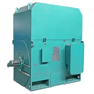
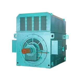
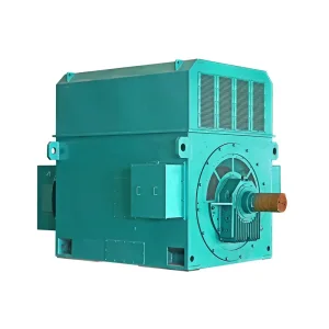
Industrial applications require robust mechanical alignment and precise structural interfaces to transmit electromagnetic torque. The classification of electric motor mounting arrangements is codified under international standards such as IEC 60034-7 (Code I / Code II) and NEMA MG1. The selection between Foot Mounting (IM B3 / IM 1001), Flange Mounting (IM B5 / IM 3001), and Foot-and-Flange Mounting (IM B35 / IM 2001) dictates the load distribution, vibration mitigation, and thermal dissipation paths of the machine system.
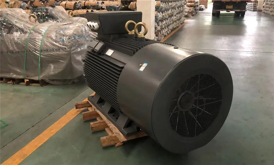
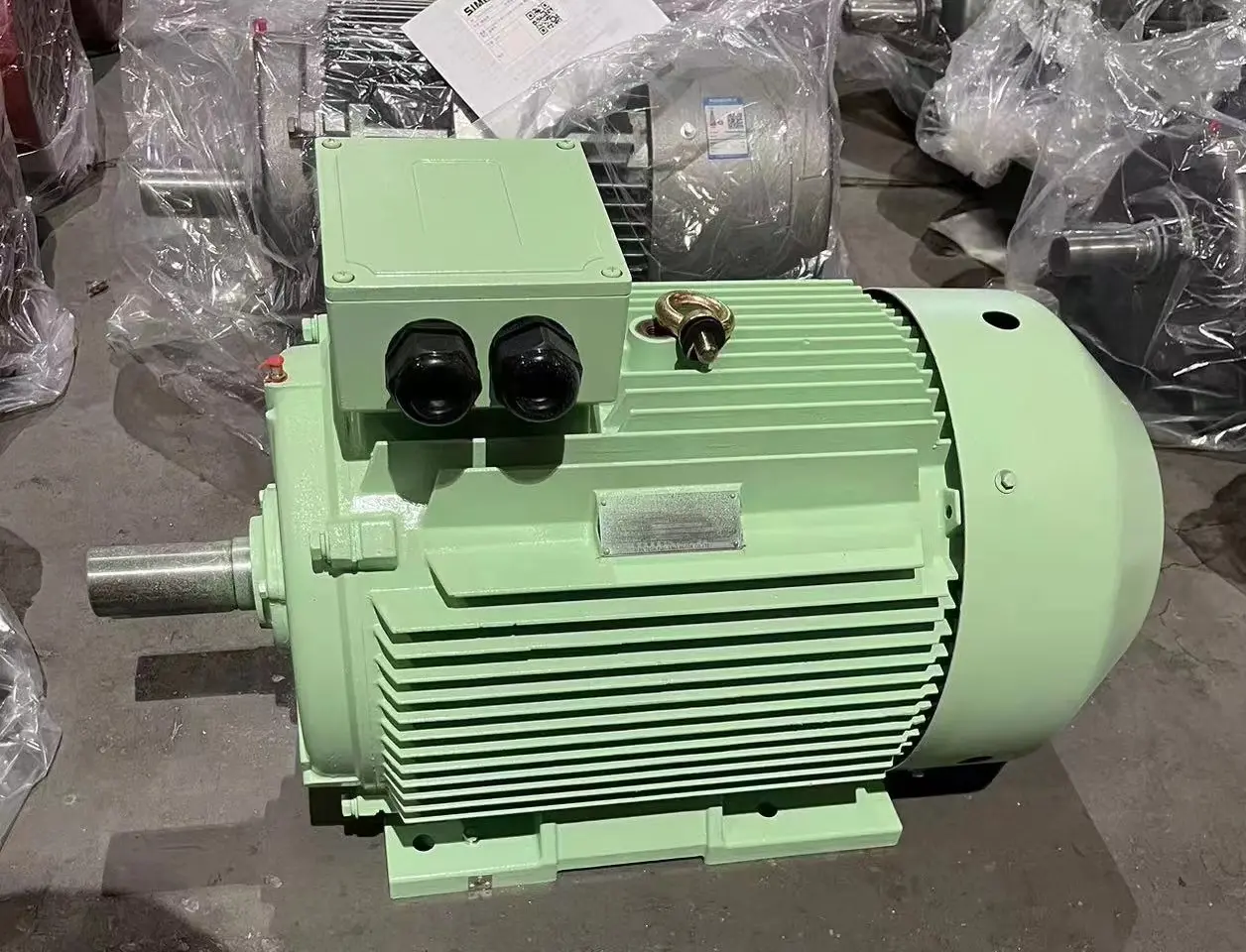
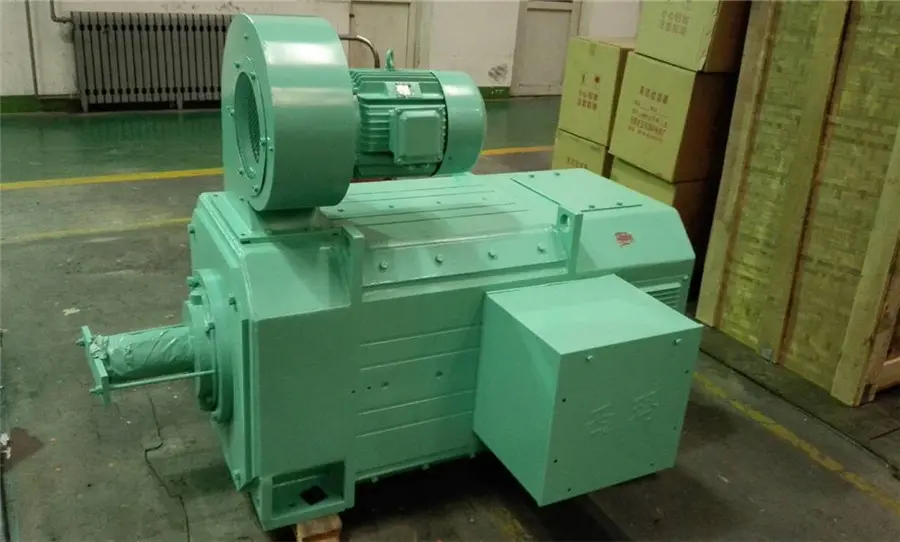
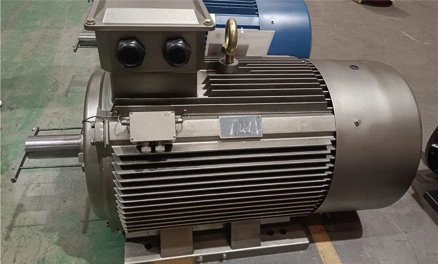
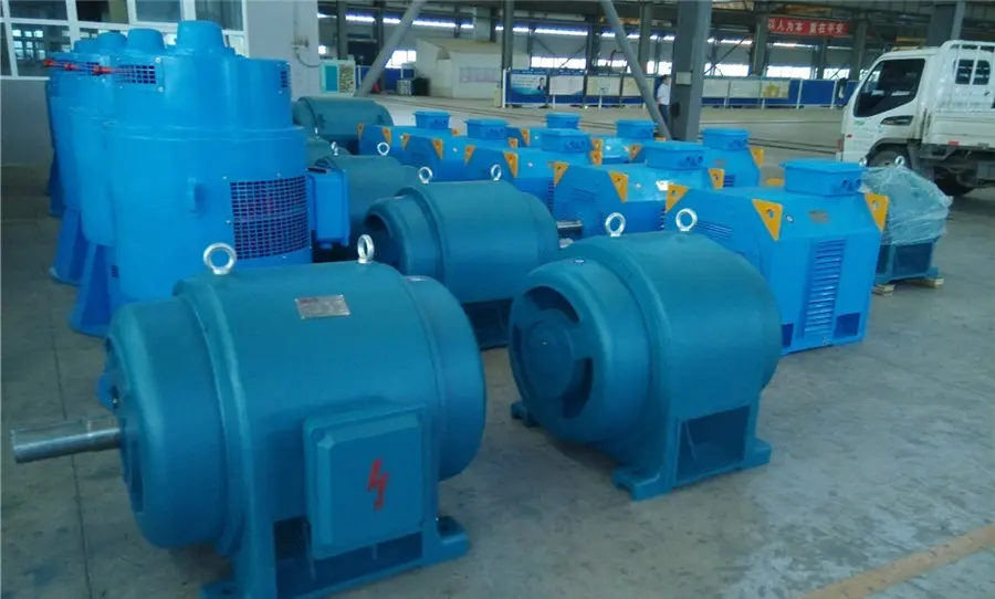
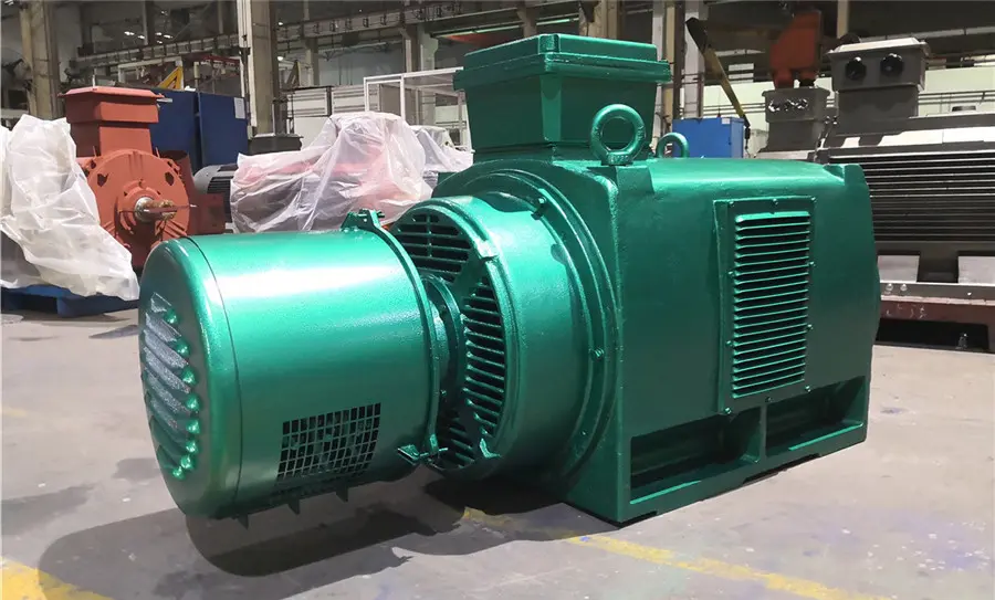
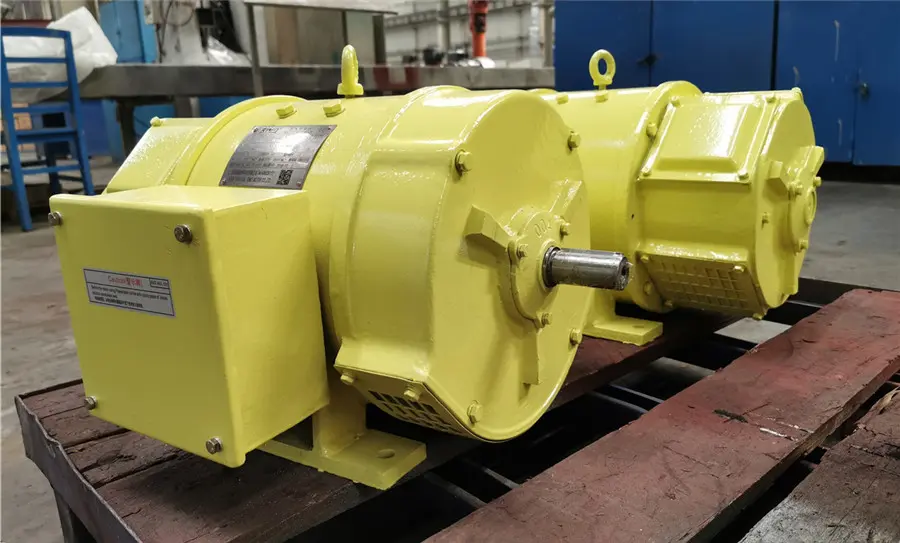
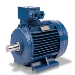
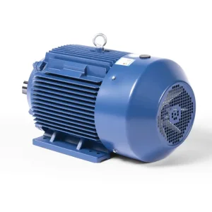
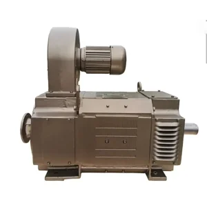
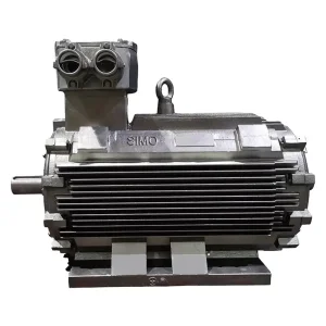
Foot Mounted Motors (IM B3): Featuring mounting feet integrated directly onto the stator frame structure, these motors are secured flat onto baseplates. B3 arrangements primarily experience radial shear stress and vertical compressive loads. They are highly favored for coupled drive setups (such as high-voltage water pump drivetrains, air compressors, and mining mills) where flexible couplings absorb minor dynamic misalignments.
Flange Mounted Motors (IM B5 / IM 14): Lacking traditional mounting feet, the motor is supported exclusively via a machined flange on the drive-end shield. B5 flanges have clearance holes and a locating register pilot that fits into the mating gearbox or pump faceplate. The mechanical integrity relies on the shear strength of the flange mounting bolts and the rigidity of the end-shield casting, making this configuration critical for direct-coupled close-coupled pumps, gear reducers, and enclosed marine propulsion auxiliary drives.
Foot-and-Flange Mounted Motors (IM B35): Combining structural support components from both topologies, the IM B35 configuration allows for double mounting support. The motor frame feet secure the vertical weight load and absorb torsional reaction forces, while the D-flange registers and couples the alignment precisely with the driven gearbox or pump casing. This is essential for large-scale, high-vibration applications such as mill drives, chemical agitators, and heavy-duty hoists.